


虚拟专用网(Virtual Private Networks)提供了一种安全的方法使多个客户网络可以共享网络服务提供商的带宽。一个VPN包含一组客户网络,它们在服务商路由器上共享一个公共的路由表。每个客户网络都与服务商网络设备的接口连接,服务商设备则将每个接口关联到一个VPN路由表。一个VPN路由表也被称为一个VRF(VPN Routing/Forwarding table)。
VRF通常被部署在服务商边缘设备(Provider Edge Device),例如MPLS VRF VPN。PE设备支持多个VPN,并且每个VPN具有独立的IP地址空间,IP地址可以重叠。不同客户的VPN网络连接着PE的不同接口,PE则根据分组的入端口区分转发所需要查找的路由表。
Multi-VRF CE功能将连接多个客户网络的任务迁移到客户边缘设备(Customer Edge Device),而CE与PE仅需要一条物理链路连接,以节省PE的端口资源。CE设备同样为每个VPN维护VRF路由表,来自客户网络的分组首先在CE上转发,需要跨越服务商网络时才会被发送给PE。
作为MCE的交换机通过不同的端口连接不同的客户网络,并将端口关联到一个VPN路由表。交换机仅支持在VLAN端口配置VRF。
MCE功能通常部署在MPLS-VRF VPN大型网络的边缘,Multi-VRF CE与MPLS标签交换以及MPLS控制层面的功能相互独立。如图1.1所示,是MPLS-VRF VPN网络的一个示例。
 图1.1 MPLS-VRF VPN网络中的MCE
Multi-VRF CE交换机可以通过多种动态路由协议与客户网络设备(Customer Device)建立路由。客户网络设备可以是路由器或以太网交换机。支持的路由协议包括OSPF,RIP,BEIGRP等。MCE交换机同样支持静态的路由配置。
MCE交换机一般需要通过不同的VLAN端口连接属于不同VPN的客户设备,连接VPN的VLAN端口需要被关联到一个VRF。客户设备不需要支持VRF。
MCE交换机可以连接一个或多个PE设备,MCE与所连接PE设备上都需要配置VRF。MCE将从客户设备学习到的路由提供给PE,并从PE学习远端客户网络的路由。
MCE与PE之间可以通过BGP,OSPF,RIP或BEIGRP等动态路由协议建立VRF路由,也可以使用静态配置VRF路由的方式。
一般情况下,MCE与PE设备属于不同的自治域。因此,本文将重点描述使用EBGP在MCE和PE之间建立VRF路由的方法。
|
功能 |
缺省配置 |
|
VRF |
无配置。 所有路由被加入缺省路由表。 |
|
VRF目标VPN扩展属性 |
无路由区分符(RD)配置。 无路由输入/输出目标(RT)配置。 |
|
VRF最大路由条目数 |
10240 |
|
VRF端口 |
无。 所有VLAN端口不关联VRF,端口路由被加入缺省路由表。 |
|
IP Express Forwarding |
硬件IP路由功能启动。 |
• 配置VRF
• 配置VPN路由
• 配置PE与CE间BGP路由
• 验证PE与CE间VRF的联通性
请参见下面的步骤,配置一个或多个VRF。
|
命令 |
目的 |
|
Switch# config |
进入交换机配置模式。 |
|
Switch_config# ip vrf vrf-name |
创建VRF,并进入VRF配置模式。 vrf-name:VRF名称,最多31个字符。 |
|
Switch_config_vrf# rd route-distinguisher |
制定VRF的路由区分符。 route-distinguisher:路由区分符,由自治域号与任意数字组成,或IP地址与任意数字组成。 |
|
Switch_config_vrf# route-target { export | import | both } route-target-extened-community |
创建VRF的输入和输出目标VPN扩展属性。 route-target-extended-community:由自治域号与任意数字组成,或IP地址与任意数字组成。 |
|
Switch_config_vrf# interface intf-name |
进入端口配置模式。 intf-name:端口名称。 |
|
Switch_config_intf# ip vrf forwarding vrf-name |
将三层接口与VRF关联。 vrf-name:VRF名称。 |
|
Switch_config_intf# exit |
退出端口配置模式。 |
|
Switch_config# ip exf |
启动IP硬件路由功能。 |
|
Switch_config# show ip vrf [ brief | detail | interface ] [ vrf-name ] |
查看VRF信息。 |
|
Switch_config#no ip vrf vrf-name |
删除已配置的VRF以及该VRF与三层接口的关联。 vrf-name:VRF名称。 |
|
Switch_config_intf# no ip vrf forwarding [ vrf-name ] |
删除三层接口与VRF的关联。 |
可以通过配置BGP,OSPF,RIP,BEIGRP或静态路由的方式在MCE设备与客户设备之间建立路由。此处以OSPF的配置为例,其它路由协议的配置基本相同。
注意:
在MCE设备上配置与客户网络连接的路由时,需要指定路由协议的VRF属性。客户设备上不需要配置VRF。
|
命令 |
目的 |
|
Switch# config |
进入交换机配置模式。 |
|
Switch_config# router ospf process-id vrf vrf-name |
启动OSPF-VRF路由,并进入配置模式。 |
|
Switch_config_ospf# network network-number network-mask area area-id |
定义OSPF网络,掩码以及区域ID |
|
Switch_config_ospf# redistribute bgp ASN |
将指定BGP网络信息转入OSPF网络。 |
|
Switch_config_ospf# exit |
退出OSPF配置模式。 |
|
Switch_config# show ip ospf |
查看OSPF协议信息。 |
|
Switch_config# no router ospf process-id |
删除OSPF-VRF路由配置。 |
参见如下配置命令:
|
命令 |
目的 |
|
Switch# config |
进入交换机配置模式。 |
|
Switch_config# router bgp autonomous-system-number |
通过指定自治域号启动BGP路由协议,并进入BGP协议配置模式。 |
|
Switch_config_bgp# bgp log-neighbor-changes |
启动BGP邻居变化日志记录。 |
|
Switch_config_bgp# address-family ipv4 vrf vrf-name |
进入VRF address family配置模式。 |
|
Switch_config_bgp_af# redistribute ospf ospf-process-id |
将OSPF网络路由信息转入BGP网络。 |
|
Switch_config_bgp_af# network network-number/prefix-length |
配置通过BGP发布的网络号和掩码长度。 |
|
Switch_config_bgp_af# neighbor address remote-as ASN |
配置BGP邻居以及邻居的自治域号。 |
|
Switch_config_bgp_af# exit-address-family |
退出address family配置模式。 |
|
Switch_config_bgp# exit |
退出BGP配置模式。 |
|
Switch_config# show ip bgp vpnv4 [ all | rd | vrf ] |
查看BGP-VRF路由信息。 |
|
Switch_config# no router bgp ASN |
删除BGP路由配置。 |
使用带vrf选项的ping命令验证PE与CE之间VRF的联通性,ping命令的使用如下。
|
命令 |
目的 |
|
Switch# ping –vrf vrf-name ip-address |
对VRF中的地址执行ping。 |
如图2.1所示是一个简单的VRF网络。S1和S2是Multi-VRF CE交换机。S11,S12,S13属于VPN1,S21,S22属于VPN2,它们都是客户设备。CE与客户设备之间配置OSPF路由,CE与PE之间配置BGP路由。本示例中详细描述了S11,S1,PE,S2和S22上的命令行配置过程,其它设备的配置与之类似。
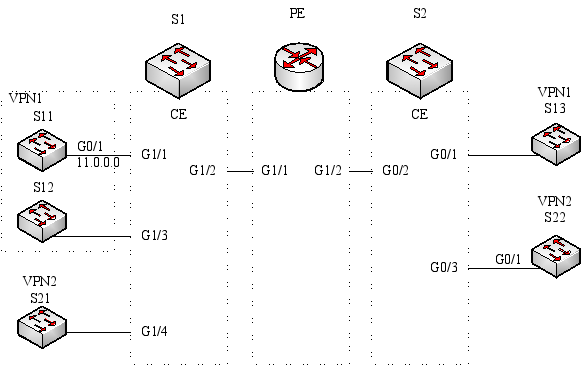 图2.1 MCE配置示例
配置连接CE设备的物理接口VLAN属性。
Switch_config# interface gigaEthernet 1/1
Switch_config_g1/1# switchport pvid 11
Switch_config_g1/1# exit
配置VLAN接口和IP地址。
Switch_config# interface VLAN11
Switch_config_v11# ip address 11.0.0.2 255.0.0.0
Switch_config_v11# exit
配置客户设备与CE间的路由协议。
Switch_config# router ospf 101
Switch_config_ospf_101# network 11.0.0.0 255.0.0.0 area 0
Switch_config_ospf_101# exit
在Multi-VRF CE设备配置VRF。
Switch#config
Switch_config# ip vrf vpn1
Switch_config_vrf_vpn1# rd 100:1
Switch_config_vrf_vpn1# route-target export 100:1
Switch_config_vrf_vpn1# route-target import 100:1
Switch_config_vrf_vpn1# exit
Switch_config# ip vrf vpn2
Switch_config_vrf_vpn2# rd 100:2
Switch_config_vrf_vpn2# route-target export 100:2
Switch_config_vrf_vpn2# route-target import 100:2
Switch_config_vrf_vpn2# exit
配置回环端口和物理端口。回环端口地址将作为BGP协议的路由器标识。
Switch_config# interface loopback 0
Switch_config_l0# ip address 101.0.0.1 255.255.255.255
Switch_config_l0# exit
S1通过G1/1端口连接S11,通过G1/4连接S21,通过Trunk端口G1/2连接PE。
Switch_config# interface gigaEthernet 1/1
Switch_config_g1/1# switchport pvid 11
Switch_config_g1/1# exit
Switch_config# interface gigaEthernet 1/4
Switch_config_g1/4# switchport pvid 15
Switch_config_g1/4# exit
Switch_config# interface gigaEthernet 1/2
Switch_config_g1/2# switchport mode trunk
Switch_config_g1/2# exit
配置交换机的三层VLAN端口,在VLAN接口上绑定VRF,并配置IP地址。S1通过VLAN21和VLAN22两个逻辑端口连接PE。VLAN11和VLAN15两个端口分别连接VPN1和VPN2。
Switch_config# interface VLAN11
Switch_config_v11# ip vrf forwarding vpn1
Switch_config_v11# ip address 11.0.0.1 255.0.0.0
Switch_config_v11# exit
Switch_config# interface VLAN15
Switch_config_v15# ip vrf forwarding vpn2
Switch_config_v15# ip address 15.0.0.1 255.0.0.0
Switch_config_v15# exit
Switch_config# interface VLAN21
Switch_config_v21# ip vrf forwarding vpn1
Switch_config_v21# ip address 21.0.0.2 255.0.0.0
Switch_config_v21# exit
Switch_config# interface VLAN22
Switch_config_v22# ip vrf forwarding vpn2
Switch_config_v22# ip address 22.0.0.2 255.0.0.0
Switch_config_v22# exit
配置CE与客户设备之间的OSPF路由。
Switch_config# router ospf 1 vrf vpn1
Switch_config_ospf_1# network 11.0.0.0 255.0.0.0 area 0
Switch_config_ospf_1# redistribute bgp 100
Switch_config_ospf_1#exit
Switch_config# router ospf 2 vrf vpn2
Switch_config_ospf_2# network 15.0.0.0 255.0.0.0 area 0
Switch_config_ospf_2# redistribute bgp 100
Switch_config_ospf_2#exit
配置CE与PE之间的EBGP路由。
Switch_config# router bgp 100
Switch_config_bgp# bgp log-neighbor-changes
Switch_config_bgp# address-family ipv4 vrf vpn1
Switch_config_bgp_vpn1# no synchronization
Switch_config_bgp_vpn1# redistribute ospf 1
Switch_config_bgp_vpn1# neighbor 21.0.0.1 remote-as 200
Switch_config_bgp_vpn1# exit-address-family
Switch_config_bgp# address-family ipv4 vrf vpn2
Switch_config_bgp_vpn2# no synchronization
Switch_config_bgp_vpn2# redistribute ospf 2
Switch_config_bgp_vpn2# neighbor 22.0.0.1 remote-as 200
Switch_config_bgp_vpn2# exit-address-family
Switch_config_bgp# exit
创建系统VLAN。
Switch_config# vlan 1,11-12,21-22
启动交换机的IP子网路由转发功能。
Switch_config# ip exf
在PE上配置VRF。
Switch#config
Switch_config# ip vrf vpn1
Switch_config_vrf_vpn1# rd 200:1
Switch_config_vrf_vpn1# route-target export 200:1
Switch_config_vrf_vpn1# route-target import 200:1
Switch_config_vrf_vpn1# exit
Switch_config# ip vrf vpn2
Switch_config_vrf_vpn2# rd 200:2
Switch_config_vrf_vpn2# route-target export 200:2
Switch_config_vrf_vpn2# route-target import 200:2
Switch_config_vrf_vpn2# exit
配置环回接口作为路由器标识。
Switch_config# interface loopback 0
Switch_config_l0# ip address 102.0.0.1 255.255.255.255
Switch_config_l0# exit
配置PE连接CE的物理接口。G1/1和G1/2分别连接S1和S2。
Switch_config# interface gigaEthernet 1/1
Switch_config_g1/1# switchport mode trunk
Switch_config_g1/1# interface gigaEthernet 1/2
Switch_config_g1/2# switchport mode trunk
Switch_config_g1/2# exit
配置PE连接S1的三层VLAN接口。
Switch_config# interface VLAN21
Switch_config_v21# ip vrf forwarding vpn1
Switch_config_v21# ip address 21.0.0.1 255.0.0.0
Switch_config_v21# exit
Switch_config# interface VLAN22
Switch_config_v22# ip vrf forwarding vpn2
Switch_config_v22# ip address 22.0.0.1 255.0.0.0
Switch_config_v22# exit
配置PE连接S2的三层VLAN接口。
Switch_config# interface VLAN31
Switch_config_v31# ip vrf forwarding vpn1
Switch_config_v31# ip address 31.0.0.1 255.0.0.0
Switch_config_v31# exit
Switch_config# interface VLAN32
Switch_config_v32# ip vrf forwarding vpn2
Switch_config_v32# ip address 32.0.0.1 255.0.0.0
Switch_config_v32# exit
配置PE的EBGP路由协议。
Switch_config# router bgp 200
Switch_config_bgp# bgp log-neighbor-changes
Switch_config_bgp# address-family ipv4 vrf vpn1
Switch_config_bgp_vpn1# no synchronization
Switch_config_bgp_vpn1# neighbor 21.0.0.2 remote-as 100
Switch_config_bgp_vpn1# neighbor 31.0.0.2 remote-as 300
Switch_config_bgp_vpn1# exit-address-family
Switch_config_bgp# address-family ipv4 vrf vpn2
Switch_config_bgp_vpn2# no synchronization
Switch_config_bgp_vpn2# neighbor 22.0.0.2 remote-as 100
Switch_config_bgp_vpn2# neighbor 32.0.0.2 remote-as 300
Switch_config_bgp_vpn2# exit-address-family
Switch_config_bgp# exit
配置VLAN并开启子网路由转发。
Switch_config# vlan 1,21-22,31-32
Switch_config# ip exf
配置VRF。
Switch#config
Switch_config# ip vrf vpn1
Switch_config_vrf_vpn1# rd 300:1
Switch_config_vrf_vpn1# route-target export 300:1
Switch_config_vrf_vpn1# route-target import 300:1
Switch_config_vrf_vpn1# exit
Switch_config# ip vrf vpn2
Switch_config_vrf_vpn2# rd 300:2
Switch_config_vrf_vpn2# route-target export 300:2
Switch_config_vrf_vpn2# route-target import 300:2
Switch_config_vrf_vpn2# exit
配置回环端口和物理端口。回环端口地址将作为BGP协议的路由器标识。
Switch_config# interface loopback 0
Switch_config_l0# ip address 103.0.0.1 255.255.255.255
Switch_config_l0# exit
S2通过G1/1端口连接S13,通过G1/3连接S22,通过Trunk端口G1/2连接PE。
Switch_config# interface gigaEthernet 1/1
Switch_config_g1/1# switchport pvid 41
Switch_config_g1/1# exit
Switch_config# interface gigaEthernet 1/3
Switch_config_g1/3# switchport pvid 46
Switch_config_g1/3# exit
Switch_config# interface gigaEthernet 1/2
Switch_config_g1/2# switchport mode trunk
Switch_config_g1/2# exit
配置交换机的三层VLAN端口,在VLAN接口上绑定VRF,并配置IP地址。S2通过VLAN31和VLAN32两个逻辑端口连接PE。VLAN41和VLAN46两个端口分别连接VPN1和VPN2。
Switch_config# interface VLAN41
Switch_config_v41# ip vrf forwarding vpn1
Switch_config_v41# ip address 41.0.0.1 255.0.0.0
Switch_config_v41# exit
Switch_config# interface VLAN46
Switch_config_v46# ip vrf forwarding vpn2
Switch_config_v46# ip address 46.0.0.1 255.0.0.0
Switch_config_v46# exit
Switch_config# interface VLAN31
Switch_config_v31# ip vrf forwarding vpn1
Switch_config_v31# ip address 31.0.0.2 255.0.0.0
Switch_config_v31# exit
Switch_config# interface VLAN32
Switch_config_v32# ip vrf forwarding vpn2
Switch_config_v32# ip address 32.0.0.2 255.0.0.0
Switch_config_v32# exit
配置CE与客户设备之间的OSPF路由。
Switch_config# router ospf 1 vrf vpn1
Switch_config_ospf_1# network 41.0.0.0 255.0.0.0 area 0
Switch_config_ospf_1# redistribute bgp 300
Switch_config_ospf_1#exit
Switch_config# router ospf 2 vrf vpn2
Switch_config_ospf_2# network 46.0.0.0 255.0.0.0 area 0
Switch_config_ospf_2# redistribute bgp 300
Switch_config_ospf_2# exit
配置CE与PE之间的EBGP路由。
Switch_config# router bgp 300
Switch_config_bgp# bgp log-neighbor-changes
Switch_config_bgp# address-family ipv4 vrf vpn1
Switch_config_bgp_vpn1# no synchronization
Switch_config_bgp_vpn1# redistribute ospf 1
Switch_config_bgp_vpn1# neighbor 31.0.0.1 remote-as 200
Switch_config_bgp_vpn1# exit-address-family
Switch_config_bgp# address-family ipv4 vrf vpn2
Switch_config_bgp_vpn2# no synchronization
Switch_config_bgp_vpn2# redistribute ospf 2
Switch_config_bgp_vpn2# neighbor 32.0.0.1 remote-as 200
Switch_config_bgp_vpn2# exit-address-family
Switch_config_bgp# exit
创建系统VLAN。
Switch_config# vlan 1,31-32,41,46
启动交换机的IP子网路由转发功能。
Switch_config# ip exf
配置连接CE设备的物理接口VLAN属性,S22通过g1/1端口连接S2。
Switch_config# interface gigaEthernet 1/1
Switch_config_g1/1# switchport pvid 46
Switch_config_g1/1# exit
配置VLAN接口和IP地址。
Switch_config# interface VLAN46
Switch_config_v46# ip address 46.0.0.2 255.0.0.0
Switch_config_v46# exit
配置客户设备与CE间的路由协议。
Switch_config# router ospf 103
Switch_config_ospf_103# network 46.0.0.0 255.0.0.0 area 0
Switch_config_ospf_103# exit
在S1设备上通过ping命令验证与S11之间vpn1的联通性。
Switch# ping -vrf vpn1 11.0.0.2
!!!!!
--- 11.0.0.2 ping statistics ---
5 packets transmitted, 5 packets received, 0% packet loss
round-trip min/avg/max = 0/0/0 ms
验证S1与PE联通性。
Switch# ping -vrf vpn1 21.0.0.1
!!!!!
--- 21.0.0.1 ping statistics ---
5 packets transmitted, 5 packets received, 0% packet loss
round-trip min/avg/max = 0/0/0 ms